
Measuring the Bandwidth and Fractional Bandwidth of an Ultrasound Array
G. Wayne Moore, B.Sc., MBA, FASE
07/14/2020
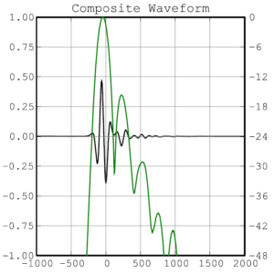
An ultrasound pulse consists of a range of frequencies, not a single frequency. For example, a pulse receive capture from a previously excited transducer element, shown as the black waveform in the diagram below (ATLAS probe testing device – www.acertaralabs.com), contains a wide range of returning echo frequencies from ~ 1MHz to ~ 15MHz (purple lines), shown in the composite spectrum on the following page. This range of frequencies is referred to as the overall bandwidth, or simply the BW of the array. However, a non-trivial portion of the measured BW is not actually useable by the ultrasound system as it contains returning signals that asymptotically approach the noise floor and are, therefore, indistinguishable from system noise.
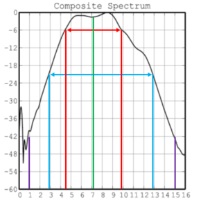
The more important and practical measurement is known as the fractional bandwidth, or FBW. As the name implies, the FBW is a fraction of the overall bandwidth of the array as described above. The FBW is a more meaningful expression of the useful frequency range of an array as it contains those echoes whose intensities can be readily distinguished from the noise floor and is, therefore, an essential indicator of expected imaging performance. The most commonly used FBW is derived by looking at the signal intensity level (Y-axis) at the -6dB points on either side of the center frequency (X-Axis), which provides us with the -6dB center frequency fc using the equation -6dB fc = (fH + fL)/2, or in our example an fc ~7.18MHz (shown as the green line). The FBW is then calculated by taking the higher and lower frequencies at the -6dB points (shown by the red lines in our example) and using the equation, -6dB FBW = 2(10/4.5 -1)/(10/4.5 +1), giving a -6dB FBW of 76.9%. Some OEM’s also take measurements at the -20dB points (shown by the blue lines in our example) as they consider intensity levels at this point a potentially better gauge of overall theoretical imaging performance. Using the same equation would yield a -20dB FBW = 2(13/3 – 1)/(13/3 +1), or a -20dB FBW of ~125%.
Contemporary 1-3 composite array materials typically produce a -6dB FBW >70% and often higher.
Fractional bandwidth is considered one of the several key performance parameters needed for the creation of a diagnostically acceptable ultrasound image; as it is related to both the overall dynamic range and spatial resolution capabilities of the ultrasound system.
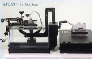
To create a diagnostically acceptable ultrasound image the behavior of the acoustic array design must be well understood. The Acertara ATLAS testing device is used by array OEMs around the world to ensure that the essential performance parameters they are receiving from manufactured arrays matches what the design anticipated.
About the Author, G. Wayne Moore:
A 30-year veteran of the diagnostic ultrasound market Wayne has held senior level positions with several major medical equipment manufacturers, including Honeywell Medical Systems and Siemens Medical Solutions. Wayne has been directly involved in the development and commercialization of more than 15 technologically intensive ultrasound systems. He is widely published in diagnostic ultrasound literature, a sought after speaker at medical imaging conferences, has served as an expert witness in multiple ultrasound litigations, and holds more than 16 United States ultrasound related patents. Wayne obtained his MBA from the University of Denver – Daniels College of Business.
He was elected as a Fellow of the American Society of Echocardiography (FASE) in 2009.
Acertara Labs
Correspondence: Dave Dallaire
1950 Lefthand Creek Lane , Longmont, CO 80501, USA
Email: ddallaire@acertaralabs.com
www.acertaralabs.com